
P-17: Primeiros testes do novo Drive
- DickonBR

- 4 de ago. de 2019
- 3 min de leitura
Atualizado: 30 de ago. de 2019
Com a PCB em mãos, comecei a montar toda a eletrônica do drive. Confesso que não foi tão trabalhoso pois esse shield realmente simplificou muito as coisas.
Peguei todos os códigos fontes dos Arduínos e feathers, diretamente do material disponibilizado pelo Joe e fiz todas as gravações de firmware, sem sequer ler os códigos, pois eu segui a risca todo seu esquema eletrônico, então nao teria porque me preocupar em revisar os códigos.
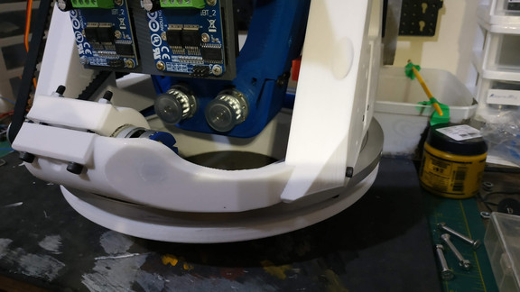
Como o body em alumínio já estava bem adiantado, resolvi colocar o drive dentro dele, para testar os encaixes e cortar o tamanho correto do eixo de 8mm, que movimentará o body.
Nos primeiros testes, o drive veio à "vida" , porem notei que não estava totalmente funcionando, como deveria.
Por algum erro, que até hoje desconheço, a parte que comanda o Arduíno Nano e o giroscópio não estavam 100% ok, fazendo o drive se comportar estranhamente.
Achei que era problema nas soldas ou conexões. Resolvi desmontar tudo e remontar na segunda PCB, afinal, eu tinha encomendado 5, da fábrica da China, então eu podia tentar pelo menos 4 vezes.
Também não funcionou.
Comecei a ficar preocupado, pois não encontrava o erro e tudo estava de acordo com o projeto.
Resolvi montar toda a eletrônica, sem o shield, de forma precária, somente para testes, e o resultado não foi dos melhores, mas ainda sim, melhor que usando o shield.
É, parecia que as PCBs que comprei, vieram com algum defeito de fabricação. Eu não poderia esperar novas PCBs. Entrei em contato com a fabrica e eles me reembolsaram o valor, algo em torno de U$ 17,00, em compras futuras, porem eu sei que não vou fazer novas PCBs no futuro, não até o momento. Enfim...
Eu precisava achar os erros. Revisei todas ligações e nada, então comecei a revisar o código dos Arduínos.
O Joe escreveu um software muito avançado e eu quase não conseguia compreender, porem nas partes iniciais, onde ele configura os pinos de entrada e saída, notei diferenças entre o código e o esquema eletrônico e tais erros me animaram, pois eram simples de resolver.
Corrigi e nada.
Uma nuvem negra caiu sobre projeto e um grande desânimo me abateu.
Comecei a perguntar nos grupos, postar fotos e nada que eles falavam me ajudava. Nem o Joe conseguiu me ajudar, afinal, ele não tinha tempo para se dedicar ao meu problema.


___________________
E-17 - New Drive First Tests
With the PCB in hand, I started assembling all the drive electronics. I confess it was not so laborious because this shield really simplified things a lot.
I got all the Arduino and feathers source code straight from the material provided by Joe and made all the firmware writes, without even reading the codes, because I followed the whole electronic scheme so I wouldn't have to worry about revising the codes. .
As the aluminum body was already well advanced, I decided to put the drive inside it, to test the fittings and cut the correct size of the 8mm shaft that will move the body.
In the first tests, the drive came to "life", but I noticed that it was not fully working, as it should.
For some mistake, which I am still unaware of, the part that runs the Arduino Nano and the gyro were not 100% ok, making the drive behave strangely.
I thought it was a problem with soldering or connections. I decided to take everything apart and reassemble on the second PCB, after all, I had ordered 5 from China factory so I could try at least 4 times.
It didn't work either.
I started to get worried because I couldn't find the mistake and everything was in accordance with the project.
I decided to assemble all the electronics without the shield, precariously, just for testing, and the result was not the best, but better than using the shield.
Yeah, it seemed like the PCBs I bought came with some manufacturing defect. I could not expect new PCBs. I contacted the factory and they reimbursed me, about $ 17.00, on future purchases, but I know I won't make new PCBs in the future, not yet. Anyway ...
I needed to find the errors. I reviewed all connections and nothing, then started revising the Arduino code.
Joe wrote a very advanced software and I could hardly understand, but in the early parts, where he configures the input and output pins, I noticed differences between the code and the electronic scheme and such errors excited me because they were simple to solve.
Fix it and nothing.
A black cloud fell over the project and a great discouragement hit me.
I started asking in groups, posting photos and nothing they said helped me. Even Joe couldn't help me, after all, he didn't have time to focus on my problem.
Pictures above.


Comentários